Setting up an IKARUS USB Interface in aeroflyRC10
Follow the steps on this page to find a possible error using an IKARUS interface.
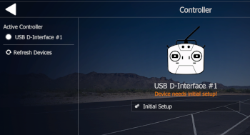
First start the aeroflyRC without the USB interface. If the software was installed correctly, the software will start with at least one model in a scenery. Now open the menu item “Controller” in the blue start screen and connect the USB interface to a USB port directly on the computer. Then click on “Refresh devices”. The name of the interface should now be displayed. If the interface in the aeroflyRC10 has not yet been used on this computer, a message will appear stating that the device requires a initial setup. Now click on “Initial Setup”. |
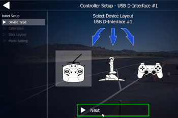 In the next step, select the pictogram that represents a transmitter for all IKARUS USB interfaces. In the next step, select the pictogram that represents a transmitter for all IKARUS USB interfaces.
Please do not use USB hubs for the initial setup. Initially no active hubs with their own power supply. |
 3rd step: 3rd step:
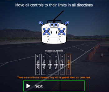
Now move all sticks and controls on the transmitter in both directions. This step is also an important way of checking whether the transmitter channels are being output/recognized correctly. The basic functions and throttle must always be followed by a bar. Transmitter channels that are not recognized remain highlighted in red and do not necessarily have to be assigned. Additional channels such as sliders and switches can only be assigned after calibration if they were recognized as a single channel bar in this step. |
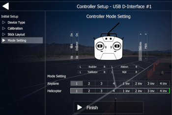
Strictly follow the further instructions up to the window shown on the right, because only here is the control mode set. Here, for example, select Mode 1 for throttle right or Mode 2 for throttle on the left. You can select “1 INV” for example if you want to fly Mode 1 with inverted throttle (idle forward). All control mode settings can be changed later.Clicking “Finish” saves the calibration. |
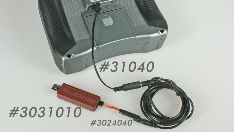 Typical sources of error when connecting an RC transmitter via the USB interface: Typical sources of error when connecting an RC transmitter via the USB interface:
- The plug connections are not 100% connected.
- You need the appropriate mono adapter for your transmitter type with a mono student socket.
- You need the signal amplifier #3024040 for your transmitter.
- You have connected the signal amplifier #3024040 even though your transmitter does not need it.
- On the three-core cable of the signal amplifier #3024040 shows the orange wire pointing outwards and not – as is correct – towards the middle of the housing on the interface.
- The transmitter is not switched on.
- Most Spektrum and Futaba transmitters, however, must be switched off when you plug in the adapter.
|
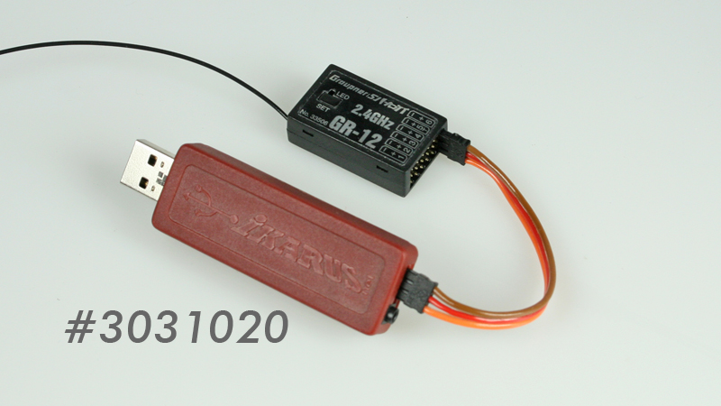 Typical sources of error when flying wirelessly with the IKARUS HoTT interface #3031020 Typical sources of error when flying wirelessly with the IKARUS HoTT interface #3031020
- The receiver or satellite used is not bound to the transmitter.
- With the three-core cable, the orange-colored wire points outwards and not – as it should – towards the middle of the housing.
- The three-core cable is not plugged into the receiver side. sum signal output of the receiver, but in a normal channel output (depending on the receiver type!).
- The receiver does not have an analog sum signal (Sum-0), but a digital one (Sum-D). A GR-12, for example, only has an analog signal. On the Gr-16, the signal must be set to Sum-0 via the transmitter. Important: A GR-12L or GR-12S only generates a digital sum signal (Sum-D). These receivers are therefore not suitable for this application.
|
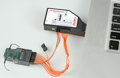 Typical sources of error when flying wirelessly with the IKARUS SimConnector #3031100 Typical sources of error when flying wirelessly with the IKARUS SimConnector #3031100
- The receiver or satellite used is not bound to the transmitter.
- The SimConnector is being operated in the wrong mode. (Download the SimConnector manual here)
- The receiver or satellite used is not compatible with the SimConnector (Find out more here)
- Click here for detailed troubleshooting related to the SimConnector.
|

 In the next step, select the pictogram that represents a transmitter for all IKARUS USB interfaces.
 3rd step:


 Typical sources of error when connecting an RC transmitter via the USB interface:
 Typical sources of error when flying wirelessly with the IKARUS HoTT interface #3031020
 Typical sources of error when flying wirelessly with the IKARUS SimConnector #3031100