


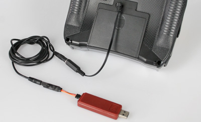
General informations:Please connect the USB interface and the cables as shown in the photos. It is important that all connections are firmly inserted. Make sure that the orange wire of the small signal amplifier points toward the center of the housing. Notes for Spektrum Important note: Please note that some Spektrum systems no longer have a 3.5 mm student jack (e.g., NX-6 or NX-8). Detailed information about this can always be found in your transmitter’s manual. In this case, we recommend the IKARUS-RC SimConnector for a Spektrum receiver. Notes for Futaba |
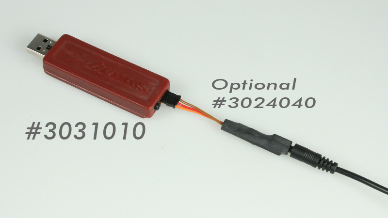 Signal amplifier #3024040. For most Spektrum and Futaba systems, the signal amplifier #3024040 included in the USB interface set should be used. If the interface is recognized with the channel number (0), please use the included signal amplifier #3024040 from the interface sets. Signal amplifier #3024040. For most Spektrum and Futaba systems, the signal amplifier #3024040 included in the USB interface set should be used. If the interface is recognized with the channel number (0), please use the included signal amplifier #3024040 from the interface sets. |
 Most Spektrum transmitters have a 3.5 mm mono jack (DSC) for connecting a simulator cable; the IKARUS interface has the matching angled 3.5 mm mono plug. Leave the transmitter turned off when plugging the adapter into the student jack. Most Spektrum transmitters will then automatically switch to Student mode and activate the Student jack.
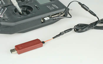 The Futaba transmitters that can be used with the aeroflyRC have a squared 6-pin socket for connecting a simulator cable. To connect a Futaba transmitter to the interface, you need the IKARUS Futaba adapter. Leave the transmitter switched off when you plug the Futaba adapter into the student socket. Most Futaba transmitters automatically switch on in student mode. To ensure that the signal is output, you must activate the student mode under “Trainer” in the system menu on most Futaba transmitters and check that “8-channel” and “PPM” are set.
Possible sources of error:
- You dont use the shown connections and adaters.
- You are combining cables and adapters from different sets.
- The transmitter is already switched on when you plug in the adapter.
- With the three-wire cable, the orange wire points outwards and not – as it should – towards the center of the housing.
- The connectors are not fully connected. Even a small gap between the plug and socket can be enough to cause a malfunction.
- If, for safety reasons, you have tested the interface according to this test and still do not see an input signal in the simulator, a broken cable may be the cause.
Please contact the sales department in this case.